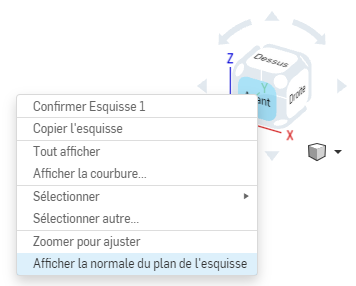
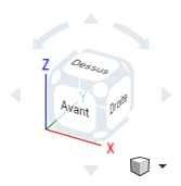
To facilitate drawing in the sketch, you can right-click on the navigation cube and click on Show the normal of the sketch plane. The 3D view will rotate to place you in front of the sketch plane in progress.
Creating your first part in OnShape
.png)
OnShape (2) - Your First Part
Creating your first part in OnShape
Pré-requis :
Logiciels :
Documentation réalisée à :
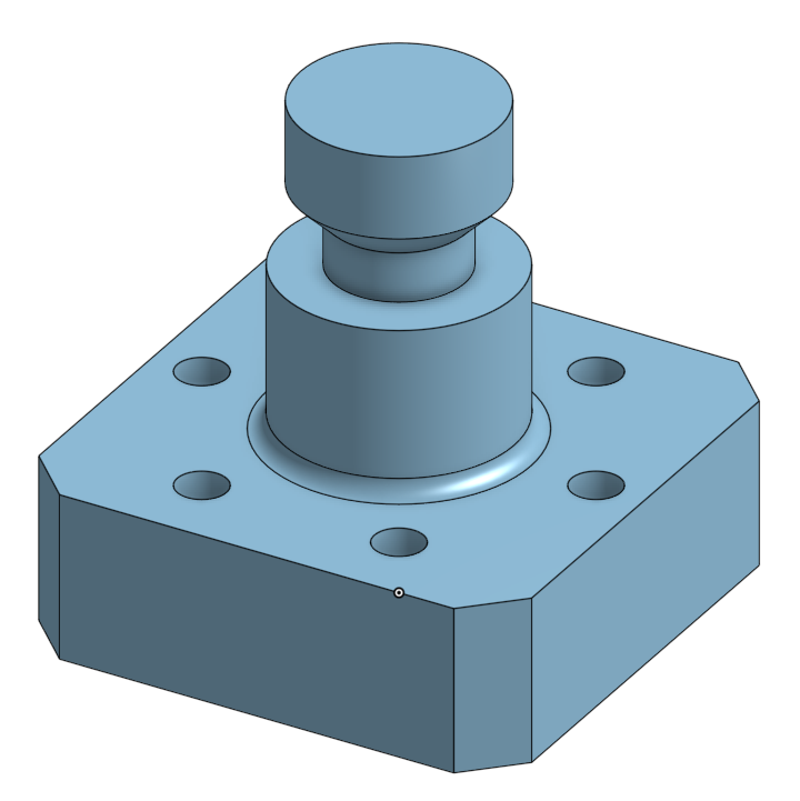
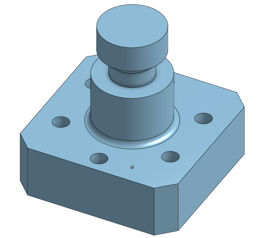
The objective of this tutorial is to discover the basic functions of OnShape by step-by-step creating the part shown above. All the functions used are not exhaustively explained, so feel free to test some options yourself.

In the top left corner, click on the Create button and then on Document

Give a name to your document and then click on OK

You should be redirected directly to the main page of your part editor. Make sure you can navigate correctly in your 3D space with your mouse before continuing.
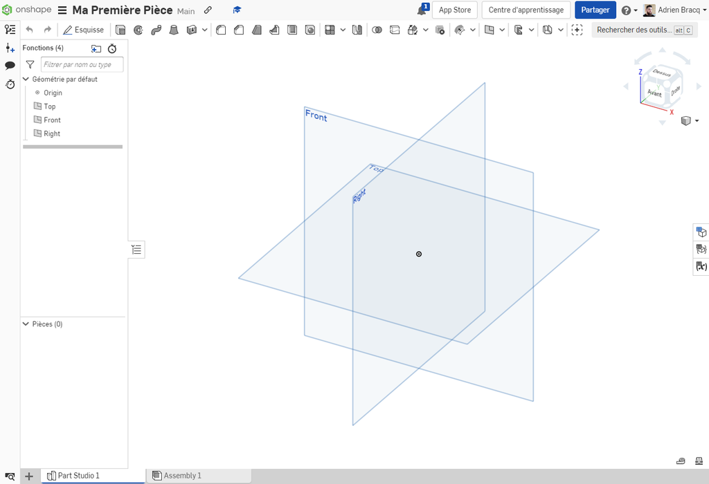

The design window is divided into 4 areas:
Area 1 is dedicated to the 3D and 2D view of your part. In 3D view, you can navigate around your part and select the elements to interact with. You also have access to the navigation cube allowing you to manage your display and its orientation very quickly.

The different parts you create and open will appear in the tabs below your window.

You can add elements to the project by clicking on the + button to the right of the tabs.

On the right, you will find the display area for the function and part tree. It details all the parts of your project (at the bottom) as well as all the functions of your current part (at the top). For better readability, you can hide this area by clicking on the button  .
.

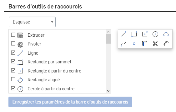
At the top of your screen, you will find the toolbar that gives you access to the functions that allow you to create and manage your parts.

This toolbar can be configured by going to My Account (click at the top right on your account) > Preferences.

Go to the toolbar and click on Sketch 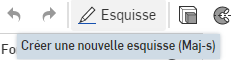 .
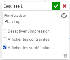
Select the Top plane as the sketch plane (double-click on the plane in question). Your selected plane should appear in your sketch window:
.
Select the Top plane as the sketch plane (double-click on the plane in question). Your selected plane should appear in your sketch window:

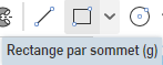
Go to the toolbar and click on Rectangle by Corners
 .
.
Draw a rectangle around the origin point as shown in the image by clicking once to define the first corner and a second time to determine the second corner. Do not click and pull (click-drag)

There are several methods to center your rectangle on the origin of your part. Read both methods carefully and test:
The square being centered on the origin (a point), click on two end vertices of the square and lastly on the origin point.
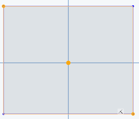
Then click on Midpoint in the constraint toolbar  .
.
You can also center the square using double symmetry. Click on two opposite vertices of the square and then on the line separating them:
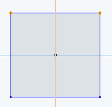
Then click on Symmetric  .
Repeat the operation for two other vertices.
.
Repeat the operation for two other vertices.

Select two adjacent sides of your square, then click on Equal.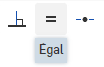

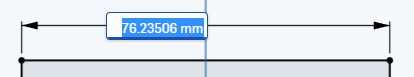
Click on the Dimension tool 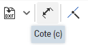 then select one of the sides of your square. Enter the value 30mm to fix your side to a dimension of 30mm.

If you are satisfied with your sketch, you can exit it by clicking on the Validate button  . You then exit the sketch mode and return to the 3D view. You can switch back to a trigonometric view by clicking on one of the corners of the navigation cube
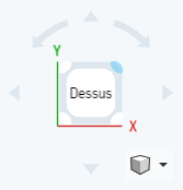

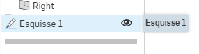
Select your previously created sketch
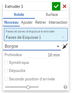
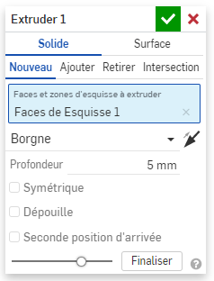
then click on Extrude 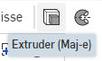 in the toolbar. In the menu that appears, make sure to select New and Blind, then change the value to 10mm.
Then Validate to exit.

Click on Sketch then double-click on the right plane to validate it as the sketch plane. Remember that you can right-click on the navigation cube to orient your view (Show the normal of the sketch plane).

Make a quick sketch of the desired shape (see illustration) using the Line tool 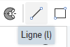 .
.

Using the Dimension tool  , dimension as indicated the sketch you previously created. Check that your sketch is fully constrained, then Validate to exit.

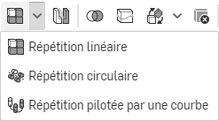
Click on the Revolve tool  then select your previously created sketch as Faces and sketch areas to sweep. Then click on Axis of Revolution
  and select the edge of the sketch around which we will perform our revolution. Make sure the Add tab is active.
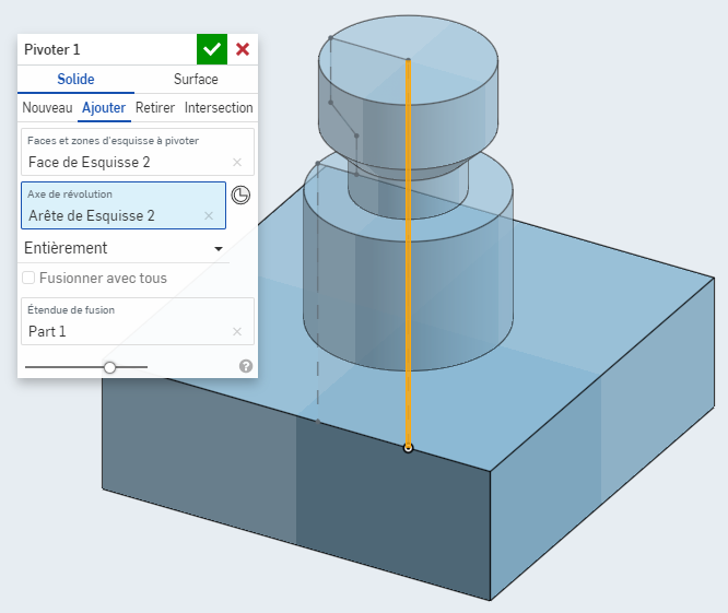
Then Validate to exit.

Create a sketch on the top plane (Top) and reproduce the sketch opposite using the Center Circle tool  . Constrain the elements as seen previously, then Validate to exit.

Select your new sketch created earlier, then click on Extrude  . In the window that appears, select the Remove tab
  , then in the End Type, select Through All
  .
If the direction of material removal is not correct, you can reverse it using the Opposite Direction button
.
If the direction of material removal is not correct, you can reverse it using the Opposite Direction button  . Then Validate to exit.
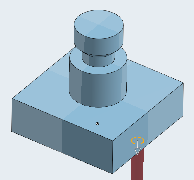

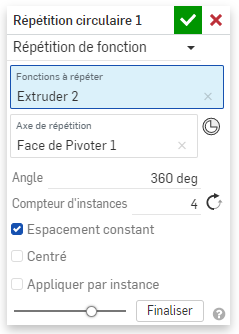
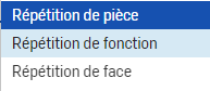
Click on the drop-down menu next to Linear Repetition and select Circular Repetition.
In the Piece Repetition drop-down menu, select Function Repetition. Indeed, what we are going to repeat circularly will be the material removal function performed earlier for our drilling.
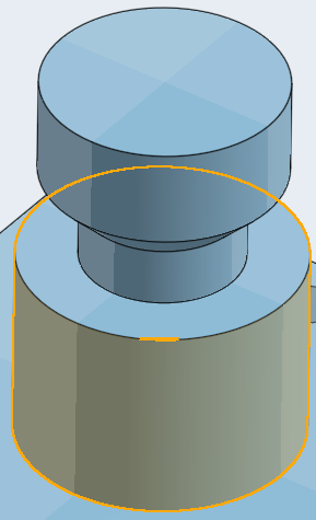
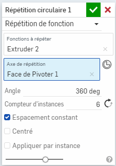
In Functions to Repeat, select your previous extrusion (the drilling) and in Repetition Axis, select one of the cylindrical surfaces at the center of the piece created earlier using the revolution tool.
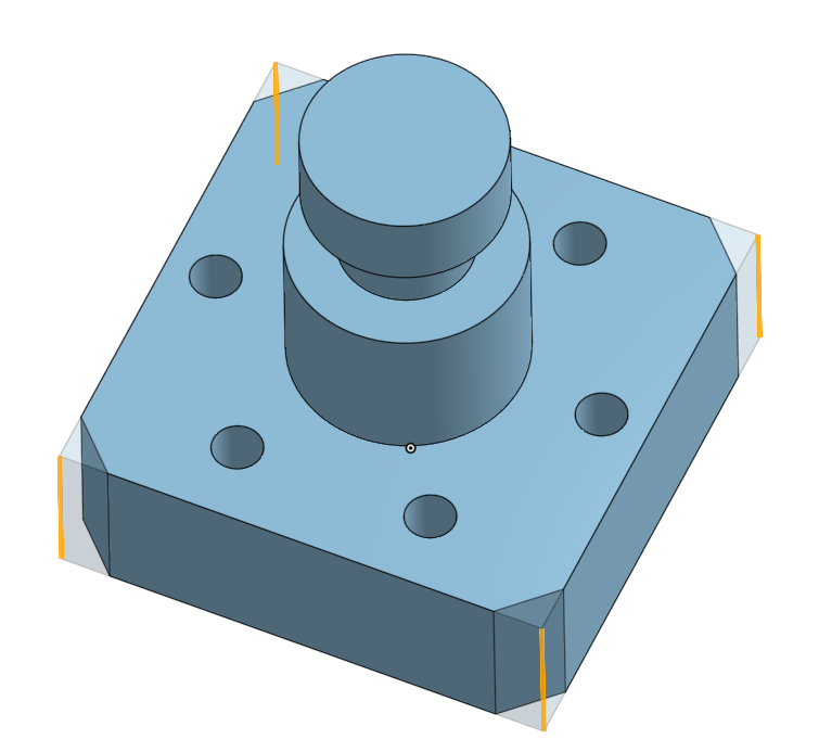
Set the instance counter to 6, then Validate to exit.
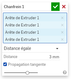
Click on the Chamfer tool  then in Entities to Chamfer, select the edges you want to chamfer.
Set a distance of 3mm for your chamfers, then Validate to exit.
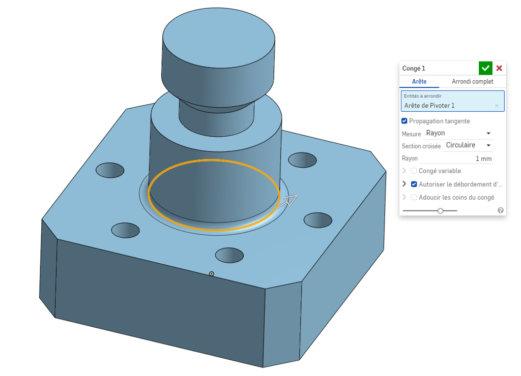
You can do the same with the Fillet tool  by selecting the base edge of the cylinder.
CAD tools are inherently parametric tools. This means that they allow you to make modifications to your parts by going back through your construction tree. This allows you to correct or add elements to your part by going back up your tree without having to redo your entire design.
For example, in our case, we will make several modifications:

In this first modification, we will change the size of the sketch, and then we will modify the height of the base.
Double-click on your first sketch (the one for your base). You will return to Sketch Editing mode for your base. Change the dimension of your square side to 40mm 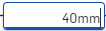 , then Validate to exit.
To modify your base height, double-click on the extrusion of your base in the construction tree, and change the height to 5mm, then Validate to exit.

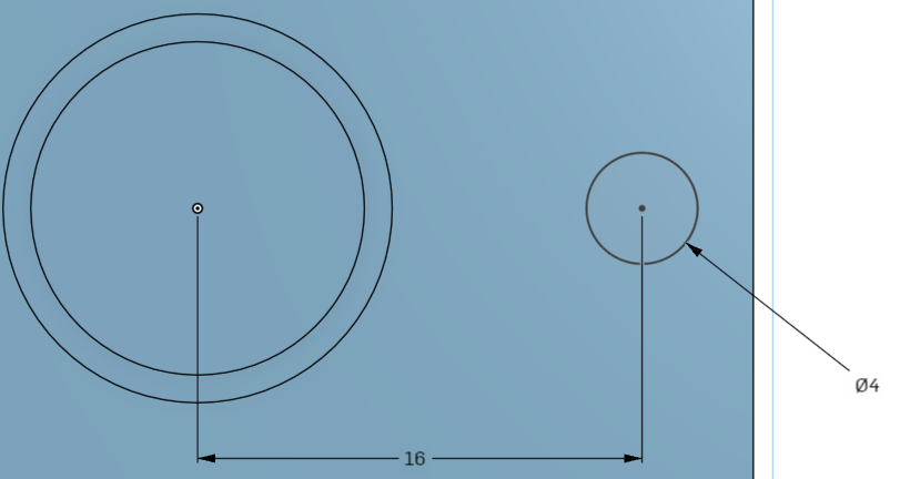
Double-click on the hole sketch to enter edit mode, and change the circle diameter to 4mm and the distance from the center to 16mm, then Validate to exit.

Double-click on the circular repetition function, then change the Instance Counter to 4 instances. Finally, Validate to exit.