Caution
If an issue arises before or during printing, or if you have any doubts about the procedure, do not hesitate to contact the FabManager of the MakerSpace.
Create a mini-project without a tutorial
.png)
OnShape (3) - Mini-Project
In this third tutorial, we will create a simple phone holder that can then be 3D printed.
Pré-requis :
Logiciels :
Documentation réalisée à :
Now that you have some basic knowledge of 3D modeling software, it’s interesting to design a small functional project on your own.
For this, we will model the phone holder below. Its creation will not be guided step-by-step, but we will give you some information to help you successfully complete this first mini-project.
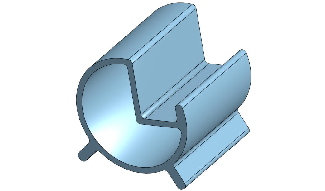

You will find the design tree of the final piece on the side.
As you can see, the piece is made up of three sketches that we will detail later, as well as 2 boss operations and one material removal operation.
The fillet operations finalize the piece.
A new operation in this design is the Shell operation, which we will detail later.

To create the main boss, you will need to create a circle with a diameter of 60mm.
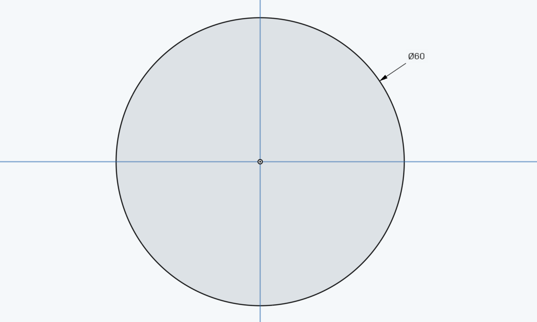
The boss will also have a depth of 60mm.

To create the feet’s boss, you will need to create the sketch below in the same plane as the main boss.
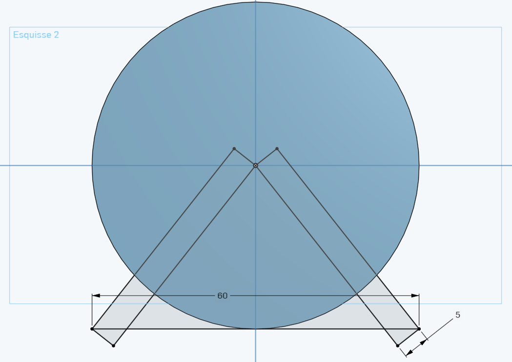
For this, you will use the Aligned Rectangle tool 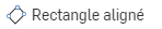 . Don’t forget to use geometric relations in the upper toolbar.
The boss will also have a depth of 60mm.

To create the material removal for the phone, you will need to create the sketch below, still in the same plane as the main boss.
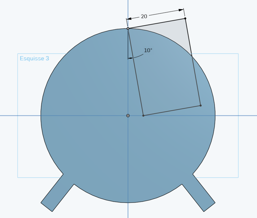
For this, you will use, as in the previous operation, the Aligned Rectangle tool. Don’t forget to use geometric relations in the upper toolbar.
You will perform a material removal Through All.

To create the central opening of the piece, we could create an offset of the outer contour. But to simplify the design, we will work with the Shell tool. This operation allows you to hollow out a piece by leaving open the faces you select and creating thin walls.
For this, click on the Shell button  in the upper banner. Then select the two opposite faces of the piece:
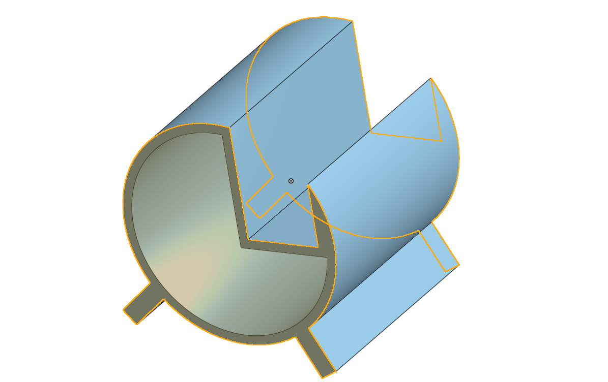
Indicate a dimension of 3mm for the shell thickness and validate.


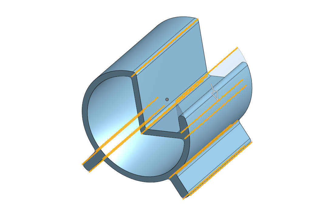
The last operation now consists of creating fillets on each edge as shown in the view below. You can select all the edges in a single operation.
The fillets will all have a radius of 2mm.
The project is complete, and you can now start printing the model.

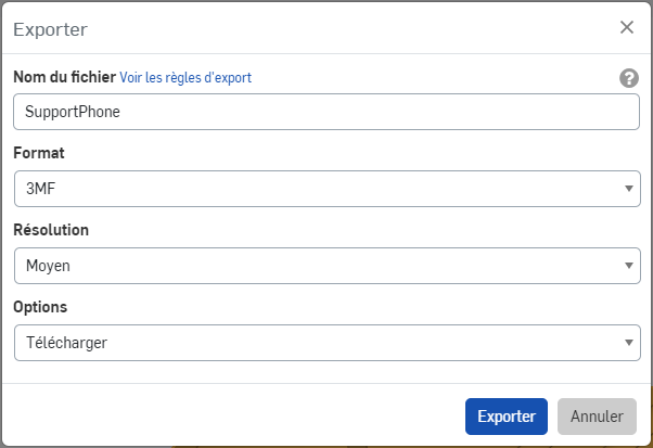
Right-click on your piece in the left toolbar, then click on Export.
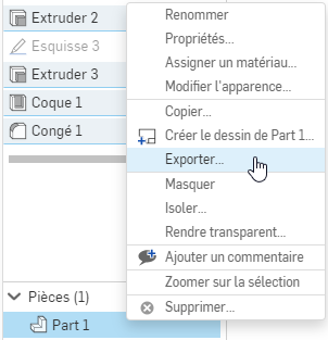
Select the 3mf file format. Save the file on a USB stick so you can bring it to the MakerSpace’s printing PC.

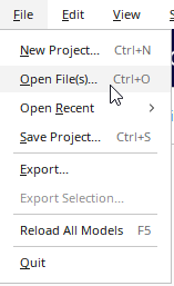
Open the Cura software  then open your 3mf format file by going to File > Open File(s)
Select the model and using the movement and rotation tools, position the file in the center of the build plate.

Make sure the selected machine and settings are correct (see below), then click on Slice at the bottom right. 

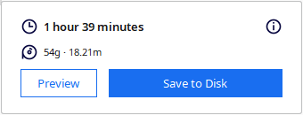
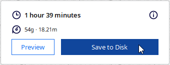
Once the slicing operation is complete, you will see an estimated printing time appear at the bottom right:

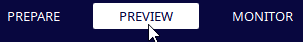
In the top bar, click on the Preview tab.
You will then have access to a view representing all the layers and manufacturing operations of the piece generated by the software. You can navigate through the layers using the right scrolling, or simulate the manufacturing of a layer using the bottom scrolling.

All that’s left is to save the machine code generated by the software to send it to the print server. To do this, simply click on Save to Disk at the bottom right and save the file in *.gcode format.

Go to the MakerSpace on the printing computer and open, if it’s not already open, the print server page.
On the page that opens, you have access to the status of all the printers on the server. In our case, we will use the SideWinder S1, S2, or S3 printers. Make sure they are properly connected. If not, notify the MakerSpace FabManager.

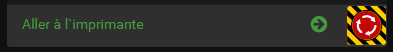
Then click on the Go to Printer button under the printer you wish to access.
You arrive at the printer management page.

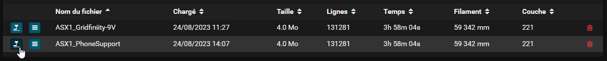
Click on Load G-Code and select the file you previously created with Cura.

Your file then appears in the list of printable files. Click on the print icon  next to your file to start printing.
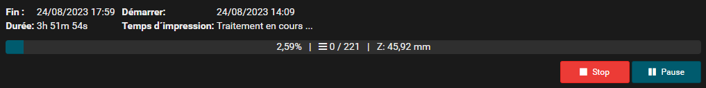
Once started, the print information updates at the top of the window, and the machine begins its heating cycle for the bed and nozzle.
All that’s left is to check the good printing of the first layers and to regularly check the proper functioning of the printing.

And there you have it! All that’s left is to wait for your print to finish! To remove the part, make sure to wait until the bed has cooled down. The part should come off on its own without any force. If that’s not the case, wait a bit longer or notify the FabManager.